
Reimagining Independent Transfers in the Home
This device is a compact lift system that enables wheel chair users by standing and pivoting to another location independently. This project was conducted over three months and sponsored by Elevated LLC who submitted for patent.
A project by Isidora Mack, Isabella Kemling, Rebekah Gatz, and Mathew Brown. University of Minnesota, 2023.
SKILLS DEVELOPED
-
Led user interviews with PTs and OTs to define biomechanical requirements
-
Designed and fabricated lifting subsystem
-
Modeled 4-bar linkage to determine actuator force requirements
-
Specified actuator capable of 1762 lb peak force
BACKGROUND
Existing Transfer Devices


Hoyer Lift
Sera Steady
EZ Stand
Research
In observing the process of how a person naturally stands, wefound that:
-
when standing up, an individual leans forward to center their weight over their feet and
-
they then push upward with their legs to rise. The device will need to move with this motion to ensure balance.
Interviews were conducted with physical therapists, occupational therapists, and the target user group on best practices for assisting with standing and pivoting. User needs include:
-
The ability to complete transfer process without straining/pulling on the shoulders
-
Balance and stability throughout the process.
-
A device that adapts to the natural standing and pivoting motions
Standing
Pivoting


Diagram showing how a caregiver helps an individual transfer using a gait belt
Problem Statement
For many wheelchair users, the most dangerous moment of the day isn't mobility, it’s transfer. Moving from a wheelchair to a toilet, bed, or chair often requires a caregiver. Existing lift systems are large, expensive, and typically require a second person to operate them. For users who are otherwise independent, this single dependency can determine whether they are able to live alone. The goal was to design an affordable, compact device that would allow a user to safely transfer from wheelchair to commode independently within the spatial constraints of a home bathroom.
This was not just a lifting problem.
It was a biomechanics, stability, footprint, and usability problem.

Frames from a video of someone standing. Insights are that the user leans forward, then begins rising and a shin rest is needed to prevent tipping forward.
Key Design Constraints
The system had to:
-
Complete connection and transfer in under 5 minutes
-
Supports a 50% of the weight of a user (up to 300 lb)
-
Powered via standard 15A wall outlet
-
Lifting the user from the trunk not the arms to prevent injury
-
Allow donning and doffing without obstruction
IDEATION

Rough sketches of some initial ideas and sources of inspiration for potential designs.
A Pugh Matrix (below) was used to evaluate and narrow down lift mechanisms, considering factors such as cost, power density, feasibility, safety, and overall viability. A hydraulic / linear-electric actuator configuration with a 4-bar mechanism provided the best balance of force capacity, compactness, and stability.

DESIGN


Free body diagram/4 bar

Dimensions for finding actuator specs
Actuator Specifications
Physical prototyping was invaluable for designing the lifting mechanism; I used PVC pipes to roughly determine the lift arm dimensions. The handle height should feel comfortable, and the gait belt attached to the arm should pull upward and slightly forward.
The first sketch below illustrates the lifting system as a 4-bar mechanism as well as a free body diagram. The primary forces include actuation force and the user’s weight acting at point A.
The other sketch shows the distance of each force from the pivot point and distance that point A moves vertically. Using this information, the minimum specifications for an actuator were determined.
Stroke Length: 4.8 inches
Required Actuator Force (statics): 750.3 lbs
Required Actuator Force (acceleration): 1762 lbs
First Design
Our first prototype design revealed several issues:
-
Footprint was too large for standard bathrooms
-
Gait belt attachment was positioned too close to the user’s face
-
Manufacturing complexity was high
-
Stability conflicted with portability
-
Shin rest should be contoured to around the legs to increase support
A major design tension emerged: Modularity vs. stability. Making the device easily disassemblable risked structural rigidity during lift. We prioritized structural integrity in the final configuration.


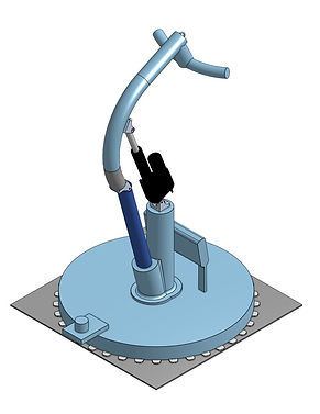
FINAL DESIGN
The final design features lockable, kick down wheels for simple transport, a smaller footprint, a 2-point attachment system to support the user, and an arm that angles more upward to pull vertically. The controls are located in the middle of the handle where the user can easily operate with their thumb. The overall design is meant to look aesthetically sleek. The clients were happy with this design and submitted it for patent (patent # US-20240358570-A1).
Future Improvements
Further improvement of this design would include user testing with the target demographic to collect feedback. The UI would also need to be improved so that even those without fine motor skills can easily control the device. This beta prototype would need to be scaled for distribution through designing for manufacturing. Finally, stability could be improved throughout the product to reliably lift a user up to 300lbs.
-
Two gait belt attachment points to accommodate a range of user heights
-
Handle
-
User controls
-
Linear-electric actuator
5. Shin rest
6. Feet placement
7. Wire casing
8. Kick down wheels
9. Rotation gears
10. Crossbar

10
1
2
3
4
5
6
7
8
9


Side View
Bottom View
Requirements Evaluation


Left: Isabella Kemling demonstrating the use of the Transfer Assist Device at the Mechanical Engineering Senior Capstone Showcase in May 2023.
Right: Rendering of the device in a bathroom to show how it could fit into a home. CAD was done in OnShape and rendering in Keyshot.