Radial Support Structure Design for a Knit SMA Tire
My undergraduate thesis focused on designing radial support elements for a non-pneumatic tire with knit shape memory alloy (SMA) treads.
A project by Isidora Mack under supervision of Dr. Julianna Abel within the Design of Active Materials and Structures Lab (DAMSL).
University of Minnesota, 2022-2023
SKILLS DEVELOPED
-
Developing a model using coding
-
Designing an experiment
-
Leveraging material science principles in design
BACKGROUND
Mobility is critical to exploring new terrains like Mars.
NASA has found that rover failures are often caused by wheel deterioration. For instance, the Curiosity Rover, which landed on Mars in 2012, experienced significant tire damage by 2013, jeopardizing its mission. Tire failure is largely due to
-
Fatigue in the noncompliant aluminum tire treads. Repetitive stress makes the material brittle, eventually leading to fractures.
-
Rough terrain on Mars.
-
Uneven load distribution between wheels


Curiosity Rover wheels.


Spring Tire from NASA Glenn Research Center being tested at the Jet Propulsion Laboratory.
NASA’s Spring Tire
NASA’s Spring Tire addresses key challenges in rover mobility, including the need for a non-pneumatic structure, minimal weight, and the ability to withstand large deformations without fatigue failure. Shape memory alloys (SMAs) are well suited to these demands due to their superelastic properties, allowing them to undergo significant strain and fully recover without permanent deformation.
NASA’s Glenn Research Center leveraged SMA technology to develop the Spring Tire, a non-pneumatic design featuring a tread made of interlocking nitinol coils. However, one limitation is its relatively smooth surface, which lacks the grousers (protruding elements that act like small cleats to increase traction against the ground) found in previous tire designs.
DAMSL’s Knit SMA Tread Design
Using knitting techniques to create the SMA tread allows for control over the surface topography and the mechanical performance, such as the auxetic nature (related to how much energy is absorbed) and the stiffness. Adjusting the knitted pattern can create raised grooves that act as grousers. The image on the right shows an example of how a custom knit can change the surface texture.
In 2019, the Design of Active Materials and Structures Lab at the University of Minnesota developed a tire prototype with a simple knit NiTi tread. This tire successfully withstood large deformations without permanent damage showing that this concept is possible.
Designing Prototype #2
My project focused on designing the support structure (radial elements) within the tire that bear the load. Prototype #2 would incorporate the chevron knit pattern and be tested outdoors on a1994 Honda Fourtax ATV. The prototype needed to meet design specifications in the table in order to successfully be tested

Swatch of knitted NiTi using a chevron pattern,


DAMSL SMA tire prototype #1.

RADIAL ELEMENT CHARACTERIZATION
There are three parameters that affect the shape of the radial element (RE). The diagram below shows each of the parameters on the radial element.
-
width
-
angle emerging from hub
-
height
A 2^k experimental design, where k = 3, was used to examine the effects of the three variables on the force-displacement results. A ninth geometry where each parameter is at its medium value was also tested.


Uncompressed sample with the background removed and key aspects highlighted.

Photo of the nitinol RE sample fully compressed.
The testing procedure involved compressing the nitinol sample using an Instron machine while recording the force and displacement. The compression sequence involved loading and unloading, increasing by 20 mm every cycle. This allowed me to observe the loading and unloading plateau of the SMA.

RESULTS
Width has the least significant impact on results. The minimum value causes an initial stiffness region. For the angle parameter, the minimum angle value causes consistently higher stiffness. The height parameter has the strongest impact on results. The minimum value greatly increases stiffness.
In order to accommodate large deformations but also support substantial forces, the medium radial element geometry was to be used for the Prototype #2 design (the green portion in the above graph). The medium geometry can displace to 60 mm, where the force supported is 0.0382 kN
TIRE ARCHITECTURE MODEL
The goal of creating a model is to understand the displacement vs. force performances for each of the different tire architectures. Future SMA-knit tire developers should be able to easily input requirements and receive the overall force as output. The following assumptions apply to this model:
-
Only the radial elements bear force, not the treads.
-
Radial elements bend in their radial plane.
-
If there’s more than one radial element at a node, each element is acting at the same point on the tire.
The curve fit function returns a force on a single radial element. The tire architecture model calculates the force supported by each engaged radial element for a given tire displacement, summing all forces in the y-direction.


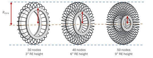
The model can be used to evaluate potential tire designs while varying the number of nodes, the radial element geometry, and the tire radius. The models to the left show examples of what possible designs could look like while holding the tire radius constant.
Modeling Potential Designs
Potential tire architectures (ranging from 1-3 radial elements/node and 45, 90, 135, and 180 nodes) were input into the model to generate force-displacement projections. The below graph shows these plots along with the 900N requirement. Any designs entirely in the red portion don’t meet requirements. Based on the results, tire architectures with the same number of total radial elements have negligible differences.


Close up of Prototype #2. Two radial elements per node can be seen
To minimize the mass, the designs with the least amount of total radial elements are optimal. Therefore, 270 total radial elements would be the most feasible option. Using 135 nodes with two radial elements per node is recommended to support the tread evenly around the tire.
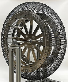
TIRE PROTOTYPE
Tire prototype #2 was developed by Berik Kallevig in 2023 based on the model I developed. The above images show the SMA non-pneumatic tire with a chevron pattern knit tread. The bottom right graph shows compression data from prototype #2 along with the modeled prediction from the tire architecture model (in red). The compression testing was performed by Berik Kallevig.